
This is the third post of a three-part blog on two-phase heat transport devices. It was supposed to be the final part, but if I get an inkling (and don’t retire first) perhaps I will continue with oscillating pipes or vapor chambers. If I do retire, it has been nice getting to know all of you over the years. (Editor’s note: We will not let her retire.)
Part 1: Thermosiphons: Pump not Included
Part 2: Heat Pipes: aka Magic Pipes
Capillary Loops: Lose that mechanical pump!
Jane Baumann
Background: Mechanically Pumped Loops (MPLs).jpg)
MPLs have been used for the removal of waste heat for many years. These loops can use single-phase or two-phase working fluids and are characterized by the presence of a mechanical pump and an accumulator. The applications are wide: automotive engine cooling, steam electric plants, refineries, and spacecraft to name a few.
The concept of cooling an automotive engine with water was first introduced by Karl Benz with the Benz Motor Car in 1886. It was actually an open loop thermosyphon resulting in the steam escaping and limiting travel distance. Closed looped systems were developed about 10 years later.
The first closed loop MPL automotive application was introduced in the early 1900s. For a chuckle, watch this 1936 Chevrolet video promoting water cooled engines.
A classic example of a single-phase MPL in the aerospace industry was hidden in the now-retired NASA space shuttle, which used the payload bay doors as radiators for the environmental control and life support system.
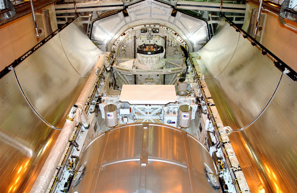 In addition to the ability to transport large amounts of heat, a benefit of a mechanically pumped cooling loop is the ability to integrate multiple heating and cooling zones. On the downside, they require mechanical pumps which require power (a valuable asset for a spacecraft) and induce vibrations into the system. They also require accumulators which can be large and heavy. And of course, if you use moving parts you run the risk that they will stop moving one day.
Debut of the Capillary Pumped Loop
As I mentioned in an earlier blog post, heat pipes have been used in the aerospace industry since the 1960s to transport heat without a cooling loop. However, as waste heat densities increased and spacecraft became larger, the need to transport larger amounts of heat over longer distances and with fewer orientation constraints pushed the limits beyond the capacity of traditional heat pipes.
In the mid 60s Francis Stenger recognized this limit and developed the concept for a Capillary Pumped Loop (CPL), a passively pumped fluid loop which eliminated the need for a mechanical pump. A CPL splits a heat pipe into separate liquid and vapor flow channels, creating distinct evaporator and condensing components. An evaporator with a porous medium provides pumping for the loop through capillary forces developed within the wick. He demonstrated the ability to transfer 700 watts of heat across distances greater than 50 feet. In the late 1970’s CPL development resumed at NASA and a series of micro-gravity experiments was conducted as Get Away Special (GAS) Experiments in the mid 1980s.

Briefly, CPLs are two-phase transport devices capable of transporting heat loads over long distances with minimal temperature drop across the system. The heat is acquired through the vaporization of the working fluid in the evaporators and rejected through condensation at a remote condenser. The system is passively pumped by means of surface tension forces developed in a porous wick structure that is located within the evaporator. A temperature-controlled two-phase reservoir (or accumulator) sets the saturation temperature of the loop, making the device variable conductance: capable of maintaining a specified temperature at the evaporators.
Compared to the MPLs, the CPL had a lot to offer: lighter weight, no vibrations, no moving parts, and variable conductance for tight temperature control. Several zero-gravity tests (CAPL) were successfully completed and the CPL was starting to catch the eye of hatchling spacecraft designers.
However, the honeymoon was cut short when early versions of CPLs (CAPL 1) displayed issues with the ability to reliably start from a deprimed condition. Technologists struggled to find a solution. The emerging technology took a huge hit, and potential customers ran as fast as they could.
The silver lining however, was that hind-sight is perfect vision: we found the tools in SINDA/FLUINT were sufficient to predict these failures had the we known to look for them. CAPL 2 introduced a “starter pump” (a small independently-heated evaporator) to clear the grooves and development continued. One of the biggest analysis challenges we all face is identifying all of the potential off-nominal operational modes that a system may encounter and designing to survive them.
Debut of the Loop Heat Pipe
Parallel to the CPL development in the United States and Europe, Yury Gerasimov and Yury Maidanik were working on related self-pumping capillary loop concepts in the former Soviet Union (Inventor's certificate № 449213, 1974). 
Similar to the CPL, the LHP is a two-phase heat transfer device that uses capillary forces in an evaporative wick structure to circulate fluid through the loop. Early LHPs used wick structures with smaller pore sizes than CPLs (sintered metal wicks versus polyethylene wicks), so they were capable of transporting high heat loads across 3 meters of adverse elevation (evaporator above condenser). A key difference between CPLs and LHPs was the presence of a wicked connection between the evaporator and the reservoir (which is usually called a “compensation chamber” in an LHP), making them very robust and self-priming. I remember the first time we were able to acquire an LHP on an R&D program I was working. After playing with it in the lab, we were quite impressed with its capabilities. However, LHPs were limited to a single evaporator and were considered to be a fixed conductance device.
Due to the cold war, the two development efforts were parallel yet independent. When Soviet leader Mikhail Gorbachev introduced glasnost (“openness”) in 1985, the door to technology exchange between the two countries opened a crack. Maidanik, Vershinin, Kholodov, Dolgirev filed a US patent in 1985 for a Heat Transfer Apparatus (the LHP).
By the early 1990’s technologists began to share information across the vast ocean, it was an exciting time for two-phase cooling geeks like Brent Cullimore and myself. I credit Don Ernst, then working at Thermacore, for bringing the CPL and LHP communities together. Being the businessman that he was, he saw this as an opportunity and opened a channel of communication for two-phase technology between the U.S. and Russia. Over the next few years it was amazing to see technologists from the U.S. and Russia come together at conferences, sharing information and lessons learned. So much progress can be made when ideas are exchanged and not hidden behind tall walls or corporate lawyers.
Ultimately the technology behind CPLs and LHPs coalesced into modern hybrid LHP technology which is robust and capable of supporting multiple evaporators and condensers. Although deprimes (full or partial) can still occur, the device can now reprime under the correct conditions. It can also be designed to provide a range of variable conductance operation using active control.
Detour: Modeling Capabilities
Synergy between FLUINT and capillary loop development
In 1982 the development of SINDA-85 was started. Guided by NASA, the development was performed by Martin Marietta (now Lockheed Martin). The co-authors were Brent Cullimore and Steve Ring, who would later go on to found CRTech together. Tidbit: Steve was also a co-author of TRASYS at the time. In 1985 FLUINT debuted, creating SINDA/FLUINT, one of the first co-solved heat transfer and fluid flow software products. Brent became involved in the development of capillary loops during the 1980s. Around 1990, I brought my heat pipe background to the team and was initiated into the “loopy” side of two phase cooling.
So what happens when you put a fluid software developer on a hardware technology development program? New features in the software!
CAPPMPs and CAPILS made their way into FLUINT to support NASA development work with CPLs, mono-groove heat pipes, and other such capillary devices of interesting in the late 1980s.
 In the early years of CRTech, Brent continued working capillary loop development and was notoriously throwing features into FLUINT over the next several years to meet our own immediate modeling needs. Over time, twinned tanks, IFACEs, and FTIEs, all made their way into FLUINT. At the time, none of us realized how valuable these would become down the road, nor did we realize what doors they would open for new development (flat-front modeling, Compartments, and so much more).
SINDA/FLUINT became the only software capable of modeling capillary loops at both the detailed component level and at the system level. The software was used to predict and help resolve issues observed with the early CAPL-1 flight experiment. To this day, it pretty much continues to be the only software with these capabilities. Without the capillary development background, it is safe to say other fluid analysis software developers probably wouldn’t know where to begin. Besides, it is a niche market which does not result in huge sales, so they probably are not even interested in pursuing it. We, on the other hand, find it interesting and challenging.
(Back on Topic)
By the mid 90’s CRTech, in collaboration with Swales Aerospace (now Orbital ATK), won a NASA SBIR to develop a Cryogenic Capillary Pumped Loop (CCPL). This was a very novel design. True backstory: it was conceived in a bar over beer and the concept was sketched on a napkin by Brent and Ed Kroliczek (Swales Aerospace).
 The Power of a Good Analyst
The feasibility of the design was demonstrated through analysis only; no hardware was built until the concept had been worked out mathematically. Funding was acquired to build a prototype and the performance matched the predictions. Over time, the program continued with a successful GAS can flight experiment on STS-95. The design required the miniaturization of CPL technology, and with no moving parts, the CCPL was able to start from a supercritical state and then cool the remote source from ambient temperature to 80K. You can learn more about the system in this publication Development of a Cryogenic Capillary Pumped Loop.
Since those days, LHP technology has advanced and is now being used in many applications from electronic cooling to spacecraft thermal control. Today LHPs can support multiple heat sources, can include deployable radiators, and can be actively controlled. Phenomena such as start-up superheat, pressure oscillations, compensation chamber cold shock, orientation sensitivities, and partial deprime and reprime can all be captured in the thermal/fluid modeling process when the analyst thoroughly understands how LHPs behave and how to model them.
At left: a radiator "breathing" (thermostatic heater effect when attached to a large cooled mass).
Although CRTech is no longer involved in LHP hardware development, we continue to monitor the new developments in the world of LHPs since we had such a strong history with them. We create tools we like to use and take every opportunity to use them through consulting work and sample model development. We also support Thermal Desktop and FloCAD users in their LHP model developments, and as a result we are always expanding our LHP simulation capabilities to meet their evolving needs.
Lately one of our focuses has been on providing insight on the ins and outs of modeling LHPs through training webinars. We are hosting a four-part series of webinars later this month which provides an overview of LHP performance and both introductory and advanced training for how to model them.
Training: All about Loop Heat Pipes
If you are at all intrigued by LHPs or if you are currently working with them, I encourage you to join us for this series. We will be serving virtual beer for your enjoyment and napkins for developing your own ideas.