Turbocharger System Sample Model
A simple model of an industrial turbocharger has been developed to illustrate key concepts for modeling systems involving more than one turbomachinery component. These concepts include the calculation of net torque, the calculation of the shaft speed that balances torque, and shaft speed transients based on transient equations of motion (namely, T = I*dw/dt).
In the case of a turbocharger, a turbine provides the torque to drive a compressor. There is no gear box in this system, though representations of gearing, gear losses, bearing losses, etc. do not represent significant modeling challenges if the data (gear ratios, torque coefficients, etc.) is readily available. Similarly, starter motors and loads (e.g., generators) can be modeled as well.
The concepts and modeling methods developed are applicable to other systems involving multiple, linked turbomachines including:
- Brayton cycles, including jet engines
- Rankine cycles
- liquid rocket turbopumps
System Description
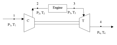
The figure below represents the system schematic.

Air at ambient pressure and 20°C enters the compressor at point 1, and is discharged at point 2 (nominally 3.5:1 pressure ratio), the engine inlet. The nominal (design point) flow rate into the compressor is 10.47 kg/s, and the nominal shaft speed is 16000 rpm. The engine is modeled as a source of hot air (with combustion products neglected for simplicity), with a constant flow rate of 0.52 kg/s.
The engine representation is very simple: it adds 5.93MW of energy to the air. The nominal flow rate through the turbine, from point 3 to 4, is the sum of the flows through the compressor and engine: 10.99 kg/s.
The nominal exhaust pressure of the turbine is 1.9MPa. The exhaust system resistance (from turbine outlet to ambient) is estimated to be equivalent to a K-factor loss of about 16.8 at the dynamic head corresponding to the turbine exhaust. (This exhaust system resistance value will be varied parametrically later to test sensitivity).
The compressor is a centrifugal compressor, with an inlet meanline diameter of 230mm, a rotor outer diameter of 474mm, and a stator outer diameter of 676mm. The turbine is a radial design, with a stator inlet diameter of 709mm, rotor inlet diameter of 541mm, and a meanline outlet diameter of 252mm.
Basic Model Description
The model was developed using Thermal Desktop® and FloCAD®. The compressor was modeled using the performance map information (flow and efficiency versus pressure ratio). EZ-XY plots of this information are provided below.


Performance Map Input for Compressor
Similarly, the performance of the turbine is plotted below. The basis for the turbine is total-static, which was defined as part of the TURBINE device information.


Solving for RPM at Zero Net Torque
In the above example, shaft speed is constant and the net torque is predicted. Often, the balance point is required: what shaft speed will result in equal but opposite compressor and turbine torques?
In SINDA/FLUINT, the Solver module can be used to find a traditional input (speed) given a traditional output (net torque), in a manner similar to the Excel goal seeking capability. The balance point was found to be about 16,050 RPM.
Shaft Speed Transient Example
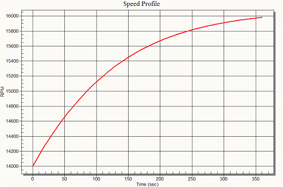
To illustrate the solution of a combined mechanical and thermohydraulic set of equations, an artificial transient is run by perturbing the shaft speed from its equilibrium value (just above 16000 rpm) to 14000 rpm … the lowest value for which turbine and compressor data are available. Initially, this lower speed will cause a net positive value of torque. The shaft will then be allowed to speed back up to its design point.
A co-solved first-order ordinary differential equation (ODE) is set up to for the current shaft RPM, following the formula T = I*dw/dt (where T is the net torque, I is the rotational inertia, w is the rotor/shaft speed, and t is time).
An event duration of 360 seconds (6 minutes) proves enough for the shaft speed to return to its equilibrium value, as shown in the responses below:


Click here to fetch the Turbocharger Example from our User Forum
