
In Stirling cycle and Gifford-McMahon (GM) cycle engines, the displacer is the piston on the cold (heat input end) of the device. GM cycles also use regenerators, as do many Stirling cycles … at least those designs intent on achieving the highest possible thermodynamic efficiency. Regenerators are also key features in pulse-tube cryocoolers, a derivative of a Stirling cycle that lacks a displacer.
Regenerators are porous bodies, usually cylindrical in shape, through which fluid passes back and forth in a cyclic motion. They are often made either of packed (but not sintered) beads, or screens stacked perpendicular to the flow direction. Regenerators are hot on one end, and cold on the other. An ideal regenerator maintains that temperature gradient: heating fluid as it enters one direction, and cooling it when it flows in the opposite direction.
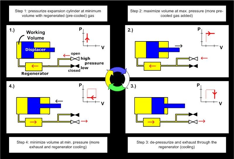
The following graphic from NIST illustrates both the regenerator and the displacer, as applied in a GM cycle:
To quote Wikipedia:
“A regenerator is difficult to design. The ideal regenerator would be: a perfect insulator in one direction, a perfect conductor in another, have no internal volume yet infinite flow area and infinite surface area. As with the hot and cold exchangers, achieving a successful regenerator is a delicate balancing act between high heat transfer with low viscous pumping losses and low dead space. These inherent design conflicts are one of many factors which limit the efficiency of practical Stirling engines.”
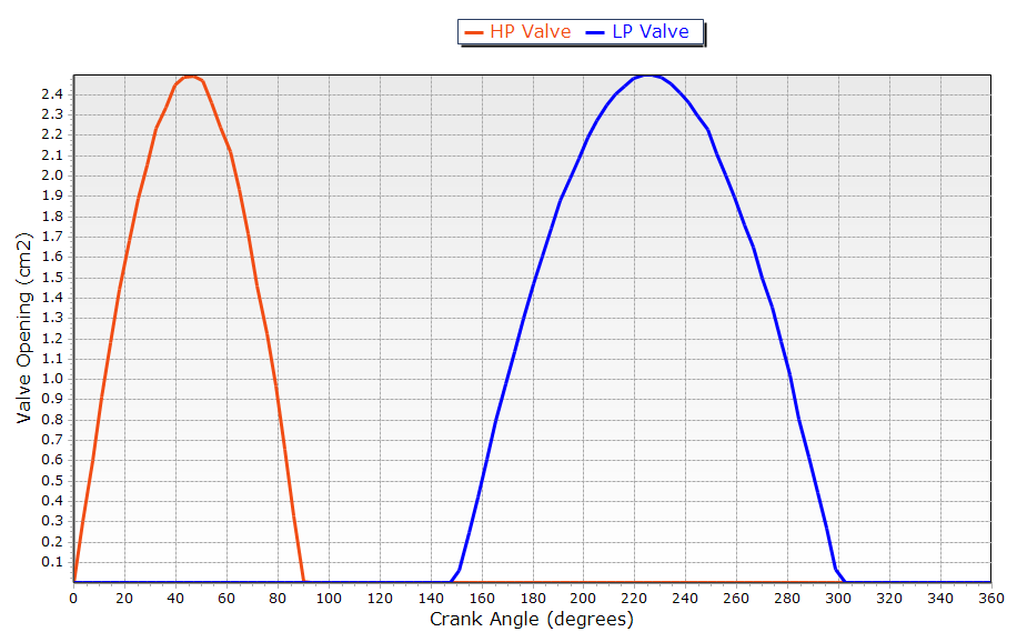
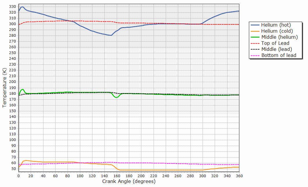
Modeling a Single Stage Helium GM Cycle
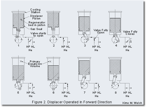
In one variation of the GM cycle, the displacer is also the regenerator: the “regenerator-displacer” is a cylinder containing a porous material. This regenerator-displacer is driven back and forth between the cold end (say of a cryocooler, perhaps used in a vacuum pump or sensor cooling application) and the hot end where heat is rejected (by exhausting out the low pressure port).
In a paper by Kimo M. Welch, the action of a single-stage R-D is nicely summarized in the figure below:
A SINDA/FLUINT (Thermal Desktop® and FloCAD®) model has been developed corresponding to the above system.
The purpose of this model is two-fold:
- Provide guidelines for regenerator modeling (the lessons learned being applicable to stationary regenerators as well)
- Provide a template or starting point for modeling similar designs
Click here to fetch the Regenerator-Displacer Example from our User Forum