
Providing Temperature Results for Structural and Stress Analyses
C&R Thermal Desktop® allows a thermal engineer and structural engineer to work side by side sharing the same CAD information or design drawings, while both engineers build distinct models that are each honed for their individual needs: even when detailed thermoelastic deformation analysis is needed. In other words, Thermal Desktop's unique model mapping methods means that the thermal model need not be the same as, nor derived from, the structural model.
While Thermal Desktop can directly import all or part of structural FEM models, that step is not necessary to accomplish the accurate export of temperatures and other thermal data back to a structural code for thermal/structural analysis. Pitfalls of competing approaches are avoided, including requirements for "one-to-one" thermal-structural model correspondence and the errors associated with using the structural model to do the mapping.
Thermal Desktop allows an appropriate thermal model to be built using geometric surfaces and solids that are not faceted, and hence do not lose surface area needed for accurate thermal radiation, convection, and contact conductance calculations. It also allows a thermally appropriate mesh that avoids unnecessary details. Thermal Desktop users can create their thermal/fluid models using whatever combinations of finite elements, finite differences, and lumped parameters suit their needs.
When the time comes to produce temperatures for structural analyzers such as NASTRAN or ANSYS, those temperatures are produced at the desired structural element points using the most accurate representation possible: the shape functions and interpolation methods used to produce the temperatures in the first place.
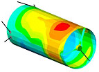
| Thermal Model | Structural Model | |
| Telescope Shell | 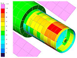 |
 |
| Mirror Support | 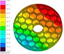 |
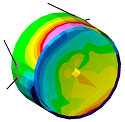 |
For example, the thermal models at the left were built independently from the corresponding structural models at the right. All models were generated from the same CAD information. The thermal model for the telescope shell uses mostly finite differences, while the thermal model for the mirror support uses mostly finite elements. In both cases, temperatures can be mapped to the independent structural model with a single command.
In fact, using the Dynamic Mode in Thermal Desktop, such mappings can be made "on the fly" as part of the analysis procedure during a transient analysis (e.g., "estimate deflections or thermal stresses every time slice") or as part a parametric sweep ("estimate thermoelastic responses of each design"). This is possible even if the structural model itself changes between each mapping. This "hands off" automated thermal/structural analysis enables design optimization, statistical design, worst case seeking, etc.