
 Geometry Preparation and Thermal Finite Element Mesher
CRTech TD Direct® fills the gap between design geometry and C&R Thermal Desktop®. TD Direct operates within ANSYS SpaceClaim®, a CAD tool that focuses on preparing geometry for analysis, just as Thermal Desktop operates within Autodesk's AutoCAD®.
With TD Direct, thermal engineers are able to solve many of the problems that have challenged them for years. Waiting for initial geometry or updates is no longer an issue as TD Direct lets thermal engineers easily create or modify geometry on their own using SpaceClaim's easy to learn push/pull interface. Our powerful mesh controls, including curved elements and swept meshes, were developed specifically for thermal modeling. TD Direct is designed to speed up model generation and design iterations without compromising accuracy, which makes it an essential companion to Thermal Desktop whether for analysis of complex geometry, evolving designs, or both.
How to Make a Better Thermal Design
TD Direct was created so thermal engineers could be more productive and operate more independently. Historically, thermal analysis can take a long time compared to other disciplines, which often means it is only included near the end of a design process. This can lead to hastily designed fixes for problems that were uncovered too late or, in the worst case, a complete redesign that puts everyone behind schedule. To avoid that outcome, some parts may be overdesigned from the beginning, and the result may be functional, but not efficient.
TD Direct is a new way forward for thermal engineers to operate more efficiently to keep pace with a changing design, allowing them to be integral to the design process. This ability to catch problems earlier and optimize the design leads to a robust and efficient product.
Geometry Manipulation and Creation
As an add-in to SpaceClaim, users gain the benefit of a push/pull interface. It is easy to learn and retain. While many CAD programs advertise what they can do for advanced users, SpaceClaim focuses on what the novice can do.
SpaceClaim can import almost every file format. While most CAD programs can import STEP and IGES files, they cannot modify them because the feature list is not included in the file. SpaceClaim does not use a feature tree, which means there it has no problem modifying STEP, IGES, or any other imported file format.
Once imported, design geometry can be healed and simplified to engineering geometry, which would exclude any thermally negligible features such as holes or rounds.
Most importantly, thermal engineers can easily create their own geometry. Key surfaces or edges from one document can be copied into another, and the geometry can be filled in from there. The analyst doesn’t need to wait on geometry from the designer.
Powerful Meshing Capabilities
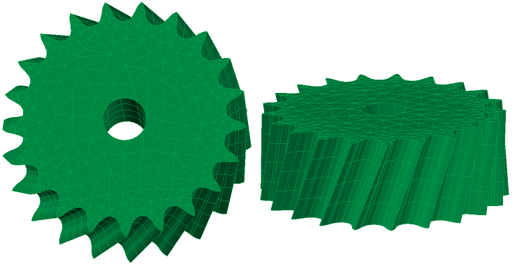
Unlike many finite element meshers that were created for structural analysis and converted for thermal use, TD Direct was created specifically for thermal analysis. The advanced mesher includes assembly options, swept meshes, and curved elements. These mesh controls are applied in TD Direct, and the mesh is created in Thermal Desktop for easy integration into any thermal model.
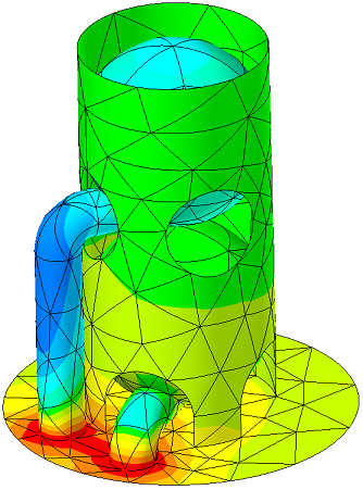
Curved elements mark the next step in thermal modeling. With "traditional" or flat finite elements, accurately capturing mass, contact areas, reflections, and internal conduction for curved geometry can result in high node density. Too many nodes slow down the model, so thermal engineers would need to find a balance between accurate geometry and model speed. Curved elements remove the need for compromise, allowing for models that are both more accurate and faster to run. See this short example showing how curved elements can reduce node count with higher accuracy, or watch this recorded webinar.
Rapid Model Creation and Iteration
It always seems that just when the thermal analysis is completed, the design changes. Early in the design process, sometimes the design changes before the model is even run. Without TD Direct, it can be an arduous process to recreate the model, assign properties, recreate contactors, etc. TD Direct makes use of tags to assign properties, mesh controls, and denote areas for Thermal Desktop operations. Once the mesh is done, it is very easy to integrate it into the rest of the thermal model. When there are changes, the thermal engineer can integrate those changes in TD Direct, resynchronize the mesh, and immediately rerun the analysis. All the information necessary for the thermal model are retained in TD Direct, meaning there is no rework. This allows thermal engineering to keep pace with other disciplines.
Speed and Accuracy
Simply put, TD Direct allows thermal engineers to be more productive. Design geometry can be simplified, the geometry can be created from scratch using a CAD program that is easy to learn, or geometry can come from both. The thermal meshes integrate easily into the rest of the thermal model, and geometry updates are passed along the dynamic link to avoid rework.
The powerful mesh controls, including curved elements, swept meshes, and anisotropic conduction, ensure the accuracy necessary for informed design decisions.
Fluid Modeling
TD Direct's meshing capabilities greatly enhance FloCAD's compartment modeling. Compartments are created inside a volume mesh, and many fluid volumes are curved. TD Direct can also be used to find the centerlines of complex piping networks that can be used in Thermal Desktop as pipe centerlines. TD Direct is not just for solids.
Ultimately, whether developing a new product or integrating existing products, giving more power to thermal engineers can only result in better designs.
Custom Meshing for Thermal Engineers
- Advanced thermal finite elements for faster solutions
- Curved surface and solid elements to accurately represent geometry with fewer nodes
- Part and Assembly meshing
- Matched meshes accelerate and improve calculations for contact or bonding
- Structured meshes that carry a mesh straight from edge to edge across a surface or face to face across a solid
- Global and local customizations of both mesh density and type
- User-specified Mesh Quality controls
- Triangular and quadrilateral surface elements
- Tetrahedral and pyramid solid elements
Integration with Thermal Desktop
- Creates active links between a Thermal Desktop drawing and multiple SpaceClaim documents
- One-button update of complete thermal/fluid model for either mesh or geometry changes
- Driving dimensions can be exported from Thermal Desktop to TD Direct to control geometry
- Names of submodels, properties, radiation analysis groups, etc. are exported to TD Direct to easily tag geometry prior to meshing
- Domain tags applied to the geometry are imported on the mesh in Thermal Desktop to allow easy and consistent application of Thermal Desktop objects such as heat loads or contactors
- Radiation with tessellated curves or exact curvature for either rapid calculations or extremely high precision specular reflections
General (SpaceClaim Engineer)
Import
- ACIS, STEP, IGES, ECAD, Rhinoceros, SketchUp, CGR, DWG, DXF, STL, OBJ, XAML, VRML, and 3D PDF (requires Adobe Acrobat 9 Pro Extended)
- Optional (with additional Data Exchange Package I): Pro/E, Inventor, CATIA v4, VDA
- Optional (with additional Data Exchange Package II): SolidWorks, Parasolid, NX
- Optional (with CATIA v5 Data Exchange Package): CATIA v5
Geometry Creation
- Create using simple sketches and push/pull interface
- Easy-to-use interface suitable for thermal engineers
- Feature recognition means all formats that are imported can be edited including STEP and IGES
Simplification and Repair
- Remove rounds, holes, fillets, and other unnecessary features
- Identify and repair gaps, small faces, missing faces, or split or inexact edges
- Identify and remove extra edges
CAE Preparation
- Midsurfacing (2D from 3D) and Extending
- Beam Extraction (e.g., centerlines for FloCAD®)
- Volume Extraction and Enclosures (preparation for fluid flow modeling)
- Imprinting and Splitting (to influence the mesh for mating faces, heaters, surface property variations, etc.)