|
This page summarizes an innovative
application of C&R's Thermal Desktop for modeling
the plume heating of a rocket nozzle.
The nozzle is convectively heated by the plume using
a heat transfer coefficient that varies along the
length and around the circumference of the nozzle.
For this example, a portion of the nozzle radiates
to a 5°K sink temperature.
Background: Rocket Plume
Heat Transfer
C&R Thermal Desktop® and
SINDA are commonly used for thermal analyses of spacecraft
and propulsion systems. Less frequently,
these tools are used for calculating the temperatures
in supersonic exhaust nozzles, such as those in rockets
or thrusters.
The temperature of the nozzle wall
is an important aspect of rocket design. The exhaust-gas
temperature typically exceeds the maximum allowable
temperature of the nozzle wall material. The ability
to estimate the wall temperature allows the design
of a cooling system.
Four types of cooling systems
can be modeled in Thermal Desktop: heat sink; thermal radiation;
even regenerative (using FloCAD®).
A difficult part of modeling the cooling system is
approximating the heat transfer from the plume to
the nozzle wall. The convective film coefficient
can be estimated through a number of methods (Bartz
equation, TDK boundary layer technique, etc);
the coefficient is highly dependent on the axial
location within the nozzle.
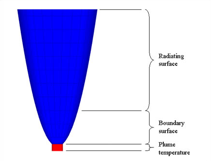
This example
shows one method of applying an axial variation to
the heat transfer coefficient within a nozzle by
using the Bartz equation to calculate the heat transfer
coefficient. The Bartz equation is [1]:

where the subscript
0 represents stagnation conditions and
Pr = the Prandtl
number,
, the characteristic
velocity,
D* = throat diameter,
rc = throat radius
of curvature in a plane which contains the nozzle
axis,
and,

where M is
local Mach number and w is
the exponent of the viscosity-temperature relation maTw. It
should be noted that the first term in the Bartz
equation (in brackets) is based on stagnation properties
and geometry and is, therefore, invariant and requires
calculation only once. The
heat transfer coefficient, hg,
is used in combination with the plume adiabatic wall
temperature and the hot wall temperature to obtain
the heat transfer rate. Since rocket plumes can
have boundary-layer recovery factors greater than
0.9, using the stagnation temperature in place of
the adiabatic wall temperature will produce slightly
conservative results. An angular
variation can be applied to model asymmetrical
flow within the nozzle due to injector non-uniformities,
also known as “streaking”.
Problem Statement
A parabolic rocket nozzle has the
following dimensions:
- Length: 195.6
cm
- Maximum diameter: 116.8
cm
- Expansion
ratio: 55:1
The wall is made of niobium
alloy C-103 with a silicide coating that gives
the nozzle an emissivity of 0.7. The first
quarter of the nozzle has a fixed temperature,
representing regenerative cooling, and the
last three-quarters radiate to a 5°K sink temperature. The
oxidizer is NTO (nitrogen tetroxide) and the
fuel is MMH (monomethyl-hydrazine) with a mixture
ratio of 1.65:1 and a chamber pressure of 8.62
atmospheres.
Thermal Desktop Model
The nozzle, shown in Figure 1, was
modeled using a single paraboloid. The top three
quarters of the paraboloid, the radiating surface,
was modeled with diffusion nodes, which are time-dependent
calculation points. The lower quarter, the boundary
surface, was modeled with boundary nodes set to 750
K. The emissivity was assumed to be that of silicide,
approximately 0.7. For boundary surface, shown in Figure 1, the
nodes of that portion of the nozzle were changed
to boundary nodes with a fixed temperature of 750
K. A
solid cylinder was used to represent the plume reference
temperature for visual clarity; this could have been
any surface or solid. The single node for the
solid cylinder was over-ridden to be a boundary node
set to the stagnation temperature of the plume. For
this model the Bartz equation was used, and
the stagnation temperature
of the exhaust was used as the reference temperature,
as discussed above.

Figure 1
- Thermal Desktop® Model
Symbols were used to define the
geometry, provide self-documentation and allow for
correction or safety factors. The Symbol Manager
window is shown in Figure 2.

Figure 2: Symbol
Manager Window
The key to modeling the nozzle heat
transfer in Thermal Desktop is a feature called “contactors”. Contactors
are a means of thermally linking high-order thermal
objects, such as surfaces and solids. Contactors
can be made between arbitrary objects, so alignment
of the node or surfaces is not necessary[2].
The contactor was created from the
nozzle to the plume
object: the order of a contactor is significant since
the geometry of the From object is used for the area
of the contactor and the dimensions for scaling. The
contactor edit window and some sub-windows are shown
in Figure 3.
Scaling can be applied to the contactor
for each dimension of the surface, angular and height
for the paraboloid. To use scaling in a contactor,
the user opens a Tabular Input window by clicking
on the appropriate button in the Conduction Coefficient
Scaling region of the Contactor Edit form (Figure
3). The scaling factor versus the proportional
dimension can be typed or pasted into the Tabular
Input window.
The scaling factor table, lower
right of Figure 3, was obtained by using CEA[3]
to calculate the exhaust properties and local Mach
numbers within the nozzle and then using a spreadsheet
set up to calculate the heat transfer coefficient
as a function of nozzle length using the Bartz equation. The
expression used in the Conduction Coefficient field
(upper right of Figure 3) allows the chamber pressure,
possibly calculated elsewhere in the model, to vary
during the solution without significant loss of fidelity. For
this purpose the expression must be output to SINDA/FLUINT. The
correction factor, Correct, can be used as a safety
factor or to correlate the heat transfer coefficient
to test data.
If asymmetric heating is present
around the circumference of the nozzle, the angular
scaling factor can be applied. For this example,
a simple sinusoidal function has been applied between
150 degrees and 210 degrees. This procedure is the
same as that described above for the height scaling
factor.

Figure 3 - Contactor
Edit Window with Expression Editor and Tabular
Input
for Coefficient Scaling by Height
Results and Discussion
The steady-state solution is presented
in Figure 4. Note the increased temperatures on the
front right side of the nozzle. The radiating section
of the nozzle shows varying wall temperatures as
a result of the changing heat transfer coefficient.
When compared to the actual system,
the convective heat fluxes for the radiating portion
of the nozzle are underestimated by about 20%. These
are reasonable results based on simplification of
the geometry (no structural reinforcements were included)
and assumptions made within CEA. The correction factor
mentioned above could be adjusted to remove this
error or provide a safety factor: a key benefit of
model parameterization.
Figure 4 - 
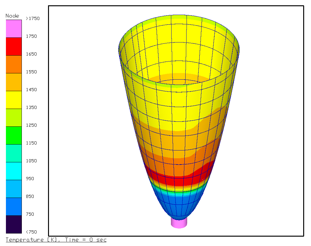
Steady-State
Results of Plume Convection in a Radiating Nozzle
Using the Bartz Equation with Streaking
Further
expansion of this model could be:
- adding
regenerative cooling in place of the fixed-temperature
condition
- adding surfaces representing
the throat (a torus, perhaps) and the combustion
chamber [4]
- adding ablative properties to
the inner wall of the nozzle or throat
- adding
a second, concentric surface around the nozzle
and mapping solid elements between the surfaces
to form a heat sink nozzle
- mapping the results to
a NASTRAN or ANSYS structural FE model
Recognition
Special
recognition must go to Dave Mohr of D&E Propulsion for his assistance
in developing this concept and example and for his
review. Also, XiaoYen Wang, of NASA Glenn Research
Center, should be recognized for asking the questions
that led to developing this example.
1 - This
definition and description of the Bartz equation
was obtained from Mechanics and Thermodynamics of
Propulsion by P. G. Hill and C. R. Peterson, 1970.
The original reference is “A Simple Equation
for Rapid Estimation of Rocket Nozzle Convective
Heat Transfer Coefficients,” D.
R. Bartz, Jet Propulsion, 37, 1, January 1957, pages
49-51.
2
- For more information on creating contactors see
the Thermal Desktop User’s Manual.
3
- CEA – Chemical Equilibrium with Applications,
a computer application written at NASA Glenn Research
Center by S. Gordon and B. McBride.
4
- Each surface in series along the
length of the nozzle requires its own contactor with
its own scaling factor, since the scaling factor
is based on the proportional length of a single surface
not a group of surfaces.
|