
Turbocharged Internal Combustion (IC) Engine Model
Open the waste gate too slowly, or inject gases from an EGR too quickly, and the compressor will surge, overloading the intercooler with warmer air without a corresponding increase in pressure (not to mention noise). Open the waste gate too quickly, or fail to get exhaust gases to the turbine fast enough, and the boost lags and the compressor might even choke when it fails to meet a sudden engine demand.
And those are just some of the transient interactions between the turbocharger and the engine. Before you can get to that point, you have to first design a compressor, turbine, and intercooler that are well matched to the engine over a wide range of operating conditions, probably assuming perfect or instantaneous controls as a starting point.
Two sample FloCAD models were built to explore both
- short time-scale events such as pressure waves within intake and exhaust runners (Detailed-level, applicable for valve or control system stability investigations), and
- long time-scale events such as boost lag (System-level, including steady-state solutions for rapid sizing).
These models illustrate key program features and capabilities, but they may also be used as templates for other engine and compressor/turbine design studies.
A library of six turbine and five compressor designs was constructed as part of these models, and the development of those turbomachine designs is also summarized.
Click here to download this sample from our support forum
The development of this sample model spawned of another IC Engine sample model designed to explore fast‐transient interactions within an engine.


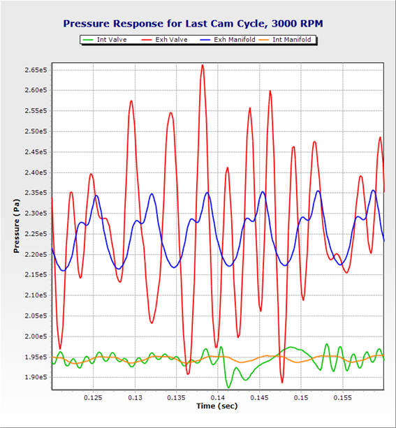
(TDC at left, center, and right of plot)